IP Connectivity Over Non-Category Cables
The Impact of IP and PoE on Electronic Security Installations
The internet protocol (IP) evolution in electronic security installations continues to accelerate. The major manufacturers in our industry are producing innovative new products and services, with most of these new technologies using IP connectivity to provide communications and control of security systems over LAN and internet connections. Where in the past many manufacturers used proprietary communications protocols to connect their devices to each other, standardized IP allows the connection of devices to common LAN infrastructure network switches and routers, and opens the gateway to remote internet connectivity allowing end users to view, control and manage far-flung devices and systems.
Along with standardized IP, most major security equipment manufacturers are including capability to power individual devices using the Power over Ethernet (PoE) standards. This provides two major benefits to both end users and installation companies. Remote devices can receive the power they need to function from the same Cat5e/6 cable that carries the IP connectivity, making device installation possible using a single, four-pair Category cable, reducing cable costs and installation time. The second major benefit is that using PoE can in most cases eliminate the need for the installation of remote power supplies or connection to remote AC power outlets, again reducing installation equipment costs and time. As our manufacturers continue to produce new and innovative products, it is most likely that these devices will have built-in PoE powering capability.
This combination of IP and PoE being utilized in today’s electronic security devices is becoming commonplace whether the devices are surveillance cameras, intercom stations, emergency telephones, evacuation systems or alarm transmitters.
Download Available
IP Connectivity Over Non-Category Cables
By David J. Engebretson, ESNT, TTT, CFOT, Network+
The Challenges of Cable Installations
Let’s consider the installation of a new IP/PoE surveillance camera in a typical commercial location. To provide the needed connectivity, installation companies will typically need to install a new Cat5e/6 four pair unshielded twisted pair (UTP) to each remote device. The proper installation of these cables requires some level of skill by the installers and care must be taken to handle the cable gently and terminate it properly using the correct type of RJ-45 connector plug on each end.
The reality of cable installation is that it will take an unknown amount of time to pull a cable from point A to point B within a specific building. There is simply no way to know how long it will require to install cables in most finished buildings before the actual installation is completed. This creates multiple potential problems and issues for installation firms and end- user clients. Careful installation companies will price a new installation with an abundant percentage of “head room” costs for pulling new cable to protect the profitability of a particular job. End users are paying the price for having new cable pulled, as a substantial portion of newly installed system costs are in wire-pulling labor. These dollars could be applied to newer and more effective electronic devices, but instead the costs of cable installation labor will usually consume 20 to 45 percent of the overall cost of the installed system. The bottom line is that end users with existing buildings are not getting the best use of their electronic security budget dollars when a large percentage of that investment is being spent on pulling new cable.
Previously Installed Cables in Existing Buildings
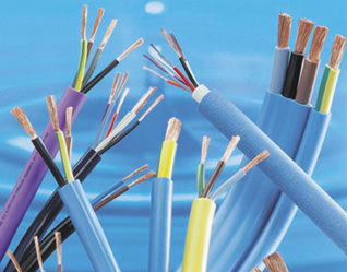
Whether commercial or residential, most end users have existing cables that were installed in the past to provide telephony, legacy analog CCTV systems, audio, intercom and other types of connectivity that were previously used by the client. These existing cables will likely include coax, 22/2 and 18/2 twisted pairs, 22/4 security cabling, and other types that can carry low-voltage signaling and electrical current. Many larger buildings or campuses have spare fiber optic connectivity between their telecom closets and/or buildings. In most cases existing cables have been left in place, even though the National Electric Code (NEC) specifies that unless cables are tagged for “future use” they are to be removed. While there are likely to be legacy low-voltage cables installed in an existing structure, in all cases buildings have AC power outlets and cabling to provide needed power for the plethora of devices that need AC.
Many device manufacturers are delivering “IP adapter” transmitter/receiver (“transceiver”) sets that can transmit 10/100 Ethernet IP signals and also deliver PoE power to remote devices using existing cabling. The use of these components in system installations where there are suitable existing cables can create powerful opportunities for both installation companies and end users.
Using IP adapter module sets can benefit installation companies as there is no longer the unknown labor element involved in the installation of new cable. Because the cost of the module sets is fixed, installation companies can predict their labor and equipment costs much more accurately, which produces more accurate system installation proposals. When using these technologies, security companies can offer end users lower-cost systems as the time and labor cost for installation is dramatically reduced. Alternatively, astute installation sales people will be able to offer end users upgraded IP devices such as 4K and HD cameras, and additional devices and systems such as intercoms, all while staying within the end user’s security system budget. Security companies can provide bigger and better systems and lower cost installations.
Manufacturers and Websites
The benefits for end users are substantial when IP adapter technologies are used. As stated above, installation labor will be dramatically reduced, yielding lower overall cost systems. When using existing cables, end users can get the needed IP and PoE connectivity without added cable costs, leveraging the monies already paid for the installation of the cables used for now-obsolete systems. The application of IP and PoE onto existing cables opens up many connectivity options for end-users to add non-security IP devices such as Wi-Fi access points and remote network switches. Suddenly, virtually all of the old cables in an end user’s walls and ceilings become IP and PoE conduits, greatly expanding connectivity possibilities. With the dramatic growth in the use of Internet of Things (IoT) devices such as smart thermostats and lighting controls, end users can benefit by reducing power usage of HVAC and lighting fixtures, saving monthly costs and reducing an end user’s “carbon footprint.”
Possibly the most important end-user benefit when IP adapter technologies are used is that clients can update and upgrade existing surveillance and security systems at the lowest overall cost, providing higher resolution surveillance video, connecting remote buildings or areas into a common security network, and improving their overall electronic security systems without expensive new cable installation costs.
Potential Markets for IP Adapter Technologies
Commercial Market Opportunities
 Virtually every existing industrial, commercial, educational and institutional client has in place legacy CCTV systems. Surveys performed by Freedonia published in 2015 estimate that there are 35 million total video surveillance cameras in use in the United States. The great majority of these are “analog” technology devices with RG-58/59 coax cables connecting the surveillance cameras to the “head end” digital video recorder (DVR). Functional coax cables are perfect candidates for IP adapter usage. A fact lost to history is that the original cabling used for the initial installations of Ethernet LAN networks in the 1980s was coaxial or “twin-ax” copper cable that was terminated in a daisy-chain loop onto each PC and device on the network. The tens of millions of existing coax cables are readily usable for IP and PoE connectivity.
Industrial and institutional campuses can utilize adapter technologies to connect security devices in separate buildings.
In the case of legacy analog CCTV cabling, it is critical to understand that in most cases if an older analog camera is to be replaced with a modern IP camera, the existing coax cables are already installed to provide connectivity to the exact locations needed, i.e. where the older camera was installed is likely to be physically close to where a new IP camera will be installed, virtually eliminating any new cable installation requirements.
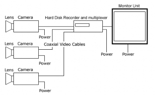 Legacy analog CCTV systems use coax cables from each camera which are “home run” to a central location for connection to recording and viewing devices. Legacy access control, intercom, music, public address and other older systems used a variety of cables, but in most all cases these cables provide either a coax or at least two individual copper conductors making them candidates for IP adapter installations. Specific IP adapter types can be utilized to put IP and PoE connectivity onto these existing cables, provided that the cables meet certain performance characteristics.
Residential Market Opportunities
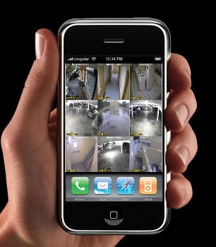
While virtually all existing commercial, institutional, and industrial buildings already have some form of video surveillance systems, installing IP cameras within and around residential homes is a “green field” opportunity for both security dealers and end users.
While legacy analog CCTV cables and the other commercially oriented cables detailed above are not common in most homes, using IP adapter sets that provide Ethernet connectivity over AC powerlines creates the ability to quickly install IP cameras. Most of today’s IP cameras can readily be accessible from “smart” phones, laptops, and other internet-connected devices. By deploying IP over AC adapter technologies, security companies can provide IP/internet video to both existing and new accounts, providing additional revenue opportunities while delivering true “peace of mind” to end users who can now remotely view their homes, families and possessions from anywhere in the world in real time or recorded formats.
IP cameras can provide authorized persons with live and recorded surveillance video on their Internet-connected smart device.
How Adapter Technologies Work
In the following discussion of cable types and IP adapter performance t’s important that readers understand that there are a number of manufacturers of IP adapters, and each will have different performance limits based on their technologies. This report details specific devices for each cable type discussed; keep in mind that other vendors usually have different performance and connectivity options for their specific IP adapters. In most cases the performance and maximum distances described below can be provided by a wide variety of manufacturers. When in doubt, check their specifications of specific IP adapter pairs. Adapter performance will be either enhanced or diminished based on the quality of the existing cables and connectors.
IP/PoE Over Coax
The most common usage of IP/PoE adapters is on existing coax cables, where a legacy analog CCTV camera is replaced by one (or more) IP cameras.
For our example we’ll take a look at the Altronix eBridge adapter sets (see Figure 1).
Figure 1. Altronix eBridge adapter sets
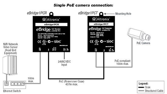
Altronix eBridge IP/PoE over coax adapters transmit Ethernet/LAN and PoE over great distances of existing or new coax cables.
In the illustration you see the basic cabling and connections when using these devices. It is important to note that these devices require that there be a PoE power source which is typically the client’s existing network switch or possibly a dealer-installed PoE switch or mid-span PoE injector. The eBridge devices get the electrical power that is required for their operation from the same PoE feed that is powering the IP camera(s) (or other IP/PoE devices) at the far end.
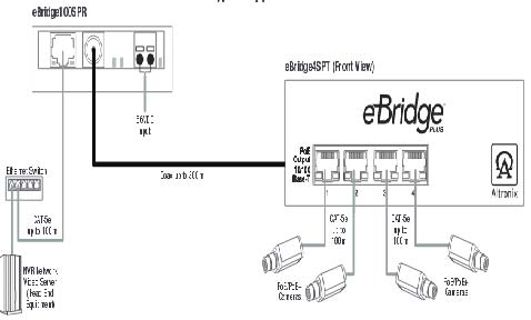
The Altronix eBridge4SPT can provide PoE power and LAN connectivity for a cluster of four IP cameras or devices.
The maximum cabling distances shown in the illustration indicate that the eBridge transceiver sets can span up to 457 meters (1499 feet) of coax cable, provided that the cable and connectors are of sufficient quality and performance. While the illustration shows the eBridge receiver on the left connected to a maximum length of 100 meters/328 feet of Cat5e/6 UTP cable, in most cases the receiver is located in the head end and connected with a short UTP jumper cable. On the far end the transceiver can also be connected to an IP camera or other device with up to 100 meters of Cat5e/6. In most cases the remote end device is installed in close proximity to the IP camera or device and only a short jumper is needed. This vendor produces a small form factor transceiver that will fit into a typical outdoor camera housing along with an IP surveillance camera.
In the situation where there are multiple IP/PoE devices to be connected at the far end, Altronix provides their eBridge connections with a four-port PoE switch to be located near the devices’ location.
In this configuration a single coax cable can provide IP connectivity and PoE power to up to four individual devices. Note that the maximum distance of coax has been reduced to 300 meters (984 feet) to allow transmission of the additional PoE current needed to power the multiple devices.
IP/PoE Over Extended UTP Cable Distances
The structured cabling standards (EIA/TIA 568) have long commanded that “Category” UTP cables cannot exceed a maximum distance of 100 meters/328 feet for a proper connection between two LAN devices such as a network switch and an IP surveillance camera. The current types of “Category” cables in use are usually of the “Cat5e” variety; in some cases Cat6 or Cat6a has been previously installed.

The usable distance of Cat5e/6 can be boosted using VeracityUSA’s OutReach Max modules.
In some specific cases it may be attractive to utilize existing Cat5e/6 UTP cable links and extend them to further lengths to provide IP connectivity and PoE power to electronic security cameras and devices. When planning such an installation, after testing the cable for proper connectivity, mid-span transceivers such as the Veracity Outreach Max can be installed to extend IP connectivity over Cat5e/6 cable for distances beyond the 100 meter (328 ft.) EIA/TIA 568 standards.
These devices function as two-port network switches. Data is retransmitted in each direction as needed, while the PoE power from the head end is passed to the PoE camera or end device. These modules are powered by the PoE feed from the head end so there is no requirement for a separate power supply or AC connection at the mid-span point. This vendor states that OutReach Max devices can be connected in series, potentially connecting remote devices to network switches up to 2 kilometers/6561 ft. of Cat5e/6.
IP Over Fiber Optic Links
One of the primary uses of fiber optic links is to provide Ethernet connectivity over distances longer than can be done using copper Category cables. Manufacturers have been producing Cat5e/6-to-fiber converters for decades, and this technology is robust, reliable and inexpensive.
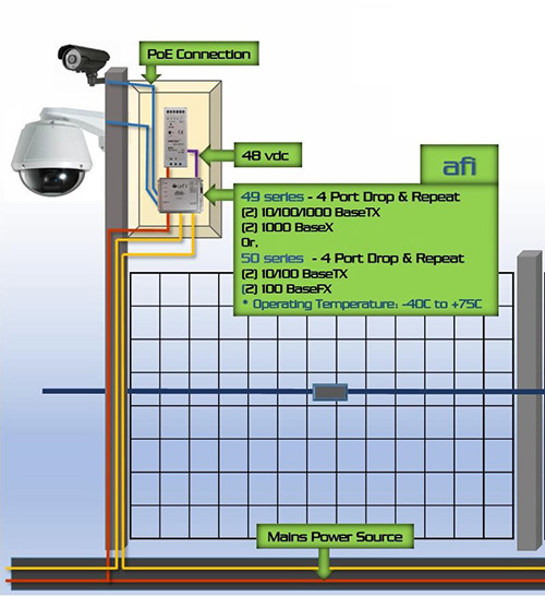
Figure 2. American FiberTek’s IP transceiver sets connected to a “multimode” fiber link
 Altronix eBridge IP/PoE over coax adapters transmit Ethernet/LAN and PoE over great distances of existing or new coax cables.
For example, Figure 2 shows American FiberTek’s #49 and 59 series of IP transceiver sets connected to a “multimode” fiber link. Multimode is a designation for the size of the “core” of the fiber, which is either 50 or 62.5 microns in diameter.
These devices function as drop and repeat transceivers. The modules are connected using two multimode fiber optic links that can be up to 1.2 miles in length. The electrical Ethernet signal is introduced into one of the modules, which converts the electrical bits into a blinking LEDor laser that travels to the other end of the fiber where it is re-converted from a light signal into its electrical mode, which is then connected to a remote device, network switch, IP camera, etc. These devices provide two-way Ethernet connectivity, but because of the construction of typical fiber optic cables (there are no metal elements), PoE cannot be transmitted over fiber links. In Figure 2, primary AC power is brought into the remote box, which is then converted into a typically 48vdc PoE power feed for the IP camera shown.
It should be noted that manufacturers produce similar devices to the above that only require a single fiber optic link for connectivity. By using multiplexing technology, a single fiber link can transmit data bi-directionally. These multiplexing devices will provide similar performance over a single fiber, however, the cost of these transceivers is substantially higher than the cost of those that utilize two separate fiber links for Ethernet transmission.
IP Over AC Power Lines
There have been tremendous improvements made in technologies that transmit and receive IP communications over AC power lines. Manufacturers such as TRENDnet and Dlink are producing inexpensive modules that plug into AC outlets and provide up to 1,200 Mbps of Ethernet connectivity.
These devices use bandwidth that is available in common AC power lines for Ethernet. Most manufacturers sell these transceivers in sets of two.
Use of these device sets is quite simple. Plug one in where the remote Ethernet connectivity is needed, and plug the other one into an outlet that is physically near the end user’s network switch equipment. A quick check of the LED indicators on the devices will indicate whether the devices will work point-to-point in a particular home or commercial structure. Each of these twin AC/IP transceivers includes a standard female RJ-45 socket for ready connection to an IP camera, network switch or other Ethernet device via a common Cat5e/6 UTP jumper cable.
In most cases these devices provide the ability to secure the communications with strong encryption, which may be automatic or manually activated. Multiples of these transceivers can be connected throughout a structure (see Figure 3) with a typical maximum of eight transceivers on a single installation when using these specific TRENDnet devices.
Figure 3. TRENDnet IP over AC adapters
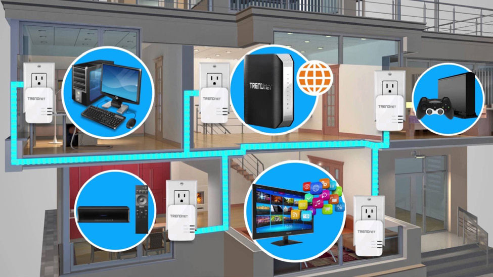
TRENDnet IP over AC adapters can quickly provide high-bandwidth LAN connectivity via modules plugged into AC outlets.
While these devices provide highly reliable Ethernet connectivity, generally these transceivers do not provide PoE so a remote device will require a separate power supply of some type.
These transceiver sets allow for very quick installation and extension of wired Ethernet connectivity without having to pull any new cables.
From a security perspective these AC/IP adapters do have a significant vulnerability: they can be unplugged just as fast as they can be plugged in. In the event of AC power failure these Ethernet connections will also stop working until the AC power is restored. Because of these factors, the best uses of these devices are in residential applications where pulling new cables for Ethernet connectivity is often particularly difficult, or in situations where a residential or commercial client needs an immediate installation of an IP camera for remote viewing and recording purposes.
IP/PoE Over Existing Intercom, Phone and Legacy Alarm Cables
IP adapter technology has progressed to the point where virtually any existing or new cable that contains at least two continuous copper conductors can be utilized to transmit and receive Ethernet and PoE power. This opens up a world of possibilities for the implementation of IP cameras and devices while dramatically reducing the need for new cable installations.
In Figure 4, Nitek 1551U transmitters and receivers can provide IP and PoE connectivity over an existing pair of conductors. The top image shows the 1551U devices connected to a PoE- enabled network switch, while the bottom illustrates how a separate PoE injector power supply can be used if the network switch doesn’t have PoE capabilities.
Figure 4.
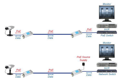
Virtually any cable with at least one pair of electrical conductors can become a pathway for IP and PoE transmissions. (Source: Nitek)
Cable Types and Performance Parameters
Probably the most common existing cable type to be used as an IP and PoE carrier is “coax,” which is a two-conductor cable with a centered solid conductor and a shielding around the white “dielectric” that surrounds the center conductor.
There are a variety of coax cables installed in buildings. In most cases RG (Radio Guide) 59 or 58 was used to connect legacy analog CCTV cameras, as well as some obsolete card reader systems. These cables will have a center conductor made of either pure copper or copper-clad steel with a diameter of 20 or 22 gauge.
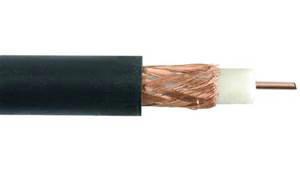 Coaxial cable is very commonly installed for legacy analog video systems.
When planning to use existing coax cables for IP and PoE transmissions there are three factors that should be confirmed before installation of the IP adapters and associated devices. First, the cable needs to be verified to be “continuous,” i.e. not cut somewhere along its length. If there is a functional analog camera attached to a specific cable and that camera is delivering an image to the head-end monitor or DVR, that is positive indication that the cable isn’t severed.
The second factor is the overall length of the cable. While the coax cable connecting most legacy analog CCTV cameras is 750 feet or less in length, in some cases security installation companies have installed analog cameras onto cables that are up to 1000 feet long. The length of a specific coax cable can be ascertained by connecting a test meter that has a Time Domain Reflectometer (TDR) function. TDRs use the constant speed of any electrical signal (186,000 miles per second) to “bounce” a test signal down a length of cable that will reflect back from the cable end. Algorithms in the TDR will deliver a very close estimate of the overall length of the cable tested. One lower cost cable tester that includes this important TDR function is the Ideal Industries VDV II Pro.
Most of the manufacturers of coax IP/ PoE adapters will list maximum distances of specific types of coax, and some will indicate that longer cable lengths will result in lower overall bandwidth capability over that particular coax cable.
All vendors’ products we have tested will transmit the 10/100 Mbps Ethernet protocol, however, this is a device language type and not a bandwidth designation or guarantee. It is quite possible for a network switch connected to an IP camera to be communicating using the 100 Mbps protocol, but the particular cable can only provide 40 or 60 Mbps of maximum bandwidth.
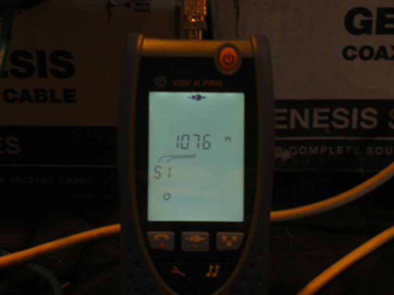 This Ideal VDV II Pro tester is connected to 1,076 feet of coax cable. (Source: David J. Engebretson)
Cable type, connector quality, cable length,and the resistance of the cable between the center conductor and the outer shield can all play a part in reducing available bandwidth. The good news is that with today’s crop of high-end HD and 4K surveillance cameras, the maximum video bandwidth that is transmitted is likely to be less than 20 Mbps per camera. The reason for this is that larger bandwidth video streams will require exponentially larger digital storage, so in most cases high-performance IP cameras have their output bandwidth “throttled” to reduce the size and cost of recorded video surveillance storage. In short, although the devices will likely use the 100 Mbps Ethernet protocol, a cable with less than 100 Mbps of bandwidth will likely function properly with today’s IP cameras and video encoders. Other electronic security devices such as alarm transmitters, IP speakers, and intercoms only transmit data on occasion and do not produce big bandwidth data streams on a 24/7/365 basis, as is the case for most IP surveillance cameras and devices.
The third measurement of an existing coax cable to check its viability as an IP/PoE carrier is the electrical resistance when tested between the center conductor and the outer shielding material. This test is performed by “shorting” one end and connecting a common volt/ohm meter set to resistance as is illustrated in Figure 5.
Figure 5. Testing electrical resistance between coax center conductor and outer shielding
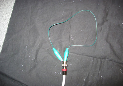
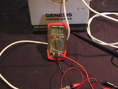
In the photos above, the left image shows the end of a coax cable being “shorted” between the center conductor and shielding, and the right image shows a volt/ohm meter connected to the far end and measuring the total resistance of the conductors. (Source: David J. Engebretson)
Cat5e/6 Cable Testing
Without the use of a sophisticated UTP “certification” tester, existing Cat5e/6 cables can be tested for basic connectivity and proper termination using an inexpensive tester such as the Byte Bros “Pocket Cat” (see Figure 6).
Figure 6. Byte Bros “Pocket Cat”
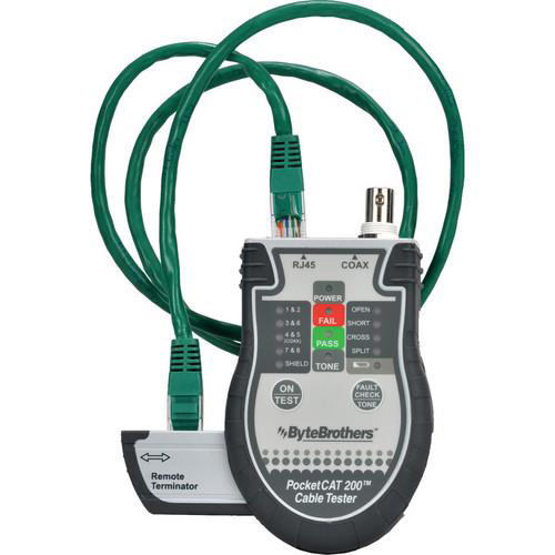
All UTP (Cat5e/6) cable testers are two-piece devices, and will verify that the individual conductors of the four-pair cables are properly terminated. (Source: Byte Bros.)
This tester requires that each end of a cable to be tested is connected to one of the two-piece tester modules. This simple tester will indicate that each of the conductors in the typical four-pair Category cable is continuous and is properly terminated. More sophisticated testers will use the same two-piece method, but can provide more information including overall cable length, presence of Ethernet and PoE and other cable measurements.
Fiber Optic Link Testing
There are three methods that can be used to verify that an existing multimode fiber optic link is of suitable performance capability to be used to transmit IP signals.
The first method is the use of a standard flashlight. Placing a fiber optic connector’s tip onto a shining flash light will produce a visible light at the other end of a multimode fiber link that is less than 2000 ft. in length. This is a “no go” test; if the light isn’t visible at the far end, the fiber link is broken in at least one place. Typically, the problem of a broken fiber link can be repaired by replacing the existing connectors on each end of the fiber link.
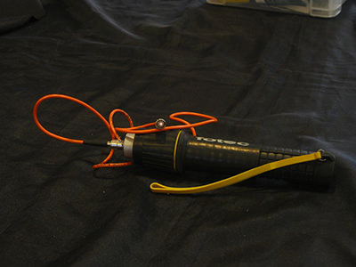 A simple bright flashlight can be used to verify that a fiber link is not broken. (Source: David J. Engebretson)
The second method requires the use of an “Optical Loss Test Set” or OLTS. This is a fiber-specific tester that requires the connection of two components. One is a light source that matches the common wavelengths used in fiber optic signaling. These wavelengths are 850, 1,300, and 1,550 nanometers. The other half of the test set is an “Optical Power Meter” that can indicate the absolute or relative light power that is received by the meter. Using this test set provides a “quality” measurement of the fiber link being examined, and the results can be compared to the specification sheets of the selected manufacturer of the IP fiber adapters to verify that performance will be within an acceptable range. Using an OLTS provides an overall quality measurement of the fiber link being tested, but does not provide any information as to the location of a problem, if one (or more) exists.
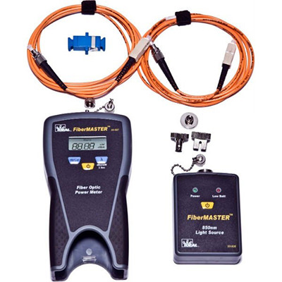 Optical loss test sets such as the Ideal FiberMASTER provide a measured test of fiber link quality. (Source: Ideal)
The third way to test a fiber link is to use an “Optical Time Domain Reflectometer” or OTDR. This is a single-ended tester that sends a laser signal into a fiber link and produces test results based on the reflections of the laser test signal that are sent back to the OTDR. The value of the OTDR is that, if used properly, problems with a fiber link can be physically located, i.e. the fiber link has high loss at a distance of 147 feet from where the OTDR is connected.
If there is a problem with a fiber link, 90 percent of the time the issue resides in one or both of the connectors that are terminated on each end of the link. A common practice is to plan to replace every fiber connector when using existing pre-installed fiber links. If the link tests are acceptable, the connectors do not need to be replaced. If the link tests are “no go” or marginal based on OLTS results, replacing the existing connectors will normally resolve the problem(s).
 OTDR “trace” graphs indicate fiber link length, and any optical loss created by connector sets, splices or installation errors. (Source: David J. Engebretson)
Connectivity Adapter Usage Examples
The following are examples of common uses of adapter technologies for electronic security applications.
IP Security Devices over Existing Fiber Optic Links
The typical types of fiber links installed within a building or campus of buildings will be either 62.5 or 50 micron core size “multimode” fibers. The most common type of fiber cable installed to connect network equipment rooms together is called “distribution” cable, and will normally have six, 12, 24 or 48 individual fiber strands underneath an outer jacket.

Most fiber optic communications utilize two fibers connected to a transceiver device on each end of a fiber link.
The standard non-security use of these fibers is the connection and continuation of IP LAN connectivity, spreading high-bandwidth Ethernet around a building or a campus of structures. To connect the fiber links to common network switch equipment that uses UTP terminations, UTP-to-fiber transceiver sets are utilized. These devices convert the electrical data signals coming to and from a network switch or UTP-connected device into blinking light signals that travel to the opposite end of the fiber link. There, the light signals are converted back into their electrical component. 10/100/1000 Mbps Ethernet is typically connected using two fiber links, with a separate “transmit” and “receive” connection on each UTP-to-fiber adapter. In some higher end network switches, small form factor pluggable (SFP) sockets that can have a two-fiber module installed are included, which can eliminate the need for separate fiber adapters for the transmission of Ethernet communications.
Because most applications use only two fibers from one telecom closet to the next, there are often a number of “dark” or unused fiber links that can be employed to carry electronic security communications. Once tested for functionality, it is a straight-forward process to add security system network switches to each telecom closet, providing rapid IP connectivity over great distances between the telecom closets.
The remote IP cameras/devices in such a system can be installed and connected to the network switch using new Cat5e/6 UTP, or adapters can be utilized to provide communications over existing cables using the technologies detailed above.
The primary advantage in using existing fiber links is the great leap in connectivity distance that can be achieved at a low cost in both adapters and installation labor. This type of configuration also provides complete separation of the “physical security” (IP cameras, access control, etc.) communications from the “enterprise” or end users’ network communications. This greatly reduces the potential for inside personnel to hack into security devices, as well as reducing the concerns of IT managers in regards to the amount of network bandwidth that will be needed to transmit surveillance video for viewing and recording.
Upgrade of Existing Analog Camera Systems
The quickest and lowest cost way to upgrade older analog CCTV systems to high-resolution IP cameras is by using coax/UTP adapter sets.
Typical analog camera systems have individual cameras connected to the head-end DVR via coax cables. This makes for an optimal situation as the coax cables are all terminated in a central location. Chances are the end user will want, at a minimum, to view and record the same surveillance video coverage areas as was provided by their analog cameras. In this scenario the older camera mounts and enclosures can often be re-used, saving labor time and equipment cost. This situation also eliminates the need for costly additional cable runs. Only short Cat5e/6 jumpers will be needed to connect the new IP cameras to the UTP/coax adapter modules.
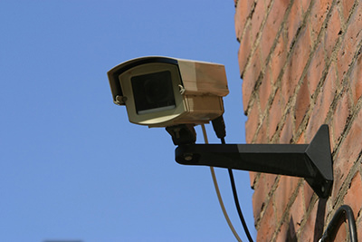 New high resolution IP cameras can be installed in existing outdoor enclosures, saving installation time and equipment cost.
In Figure 7, the IP/coax transceivers are powered by a PoE network switch. As the IP cameras are likely to also use PoE, system designers and specifiers need to calculate the aggregate wattage of PoE required to power all connected adapters, IP cameras and other end devices to ensure proper performance.
Figure 7. Multiple PoE camera connection
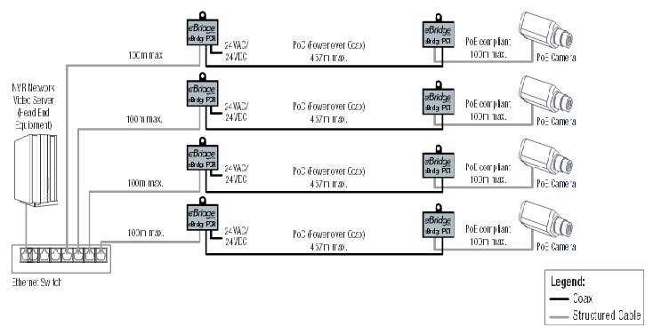 Multiple Altronix eBridge adapter sets can be connected to numerous existing coax cables. (Source: Altronix)
To replace the recording function of the old DVR, many IP camera and video encoder manufacturers are building their Internet-connected IP cameras can be remotely viewed on tablets, smart phones and PCs.) products with SD or micro-SD card slots. With a proper SD/ micro card installed, cameras can be programmed to record their own video that can be accessed by the end user with a LAN or internet-connected device that has the proper software or “app” installed. This type of recording technology does not depend on failure-prone computer hard drives and virtually eliminates use of the client’s LAN and/or internet bandwidth. SD-equipped IP cameras and encoders will only require substantial network bandwidth when camera video is being viewed live or during playback of recordings. SD card video recording is not a panacea for all end users, as the amount of recorded video will likely be two weeks or less based on the settings of the camera and the storage size of the SD cards installed.
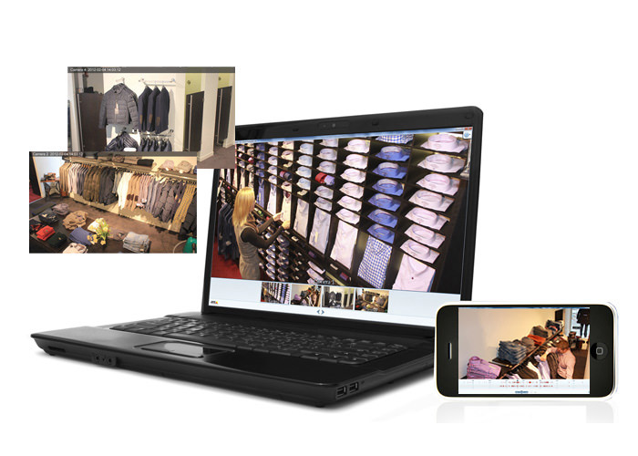
Internet-connected IP cameras can be remotely viewed on tablets, smart phones and PCs. Some vendors’ IP video devices can be programmed both to record on their “local” SD card and to send a video stream to an NVR or Network Attached Storage (NAS) unit.
In short, upgrades from older analog to IP surveillance cameras can be quick and simple when using coax/UTP adapter sets. The only concern is the quality of the existing cables, which can be quickly tested as detailed above.
IP over AC Power Lines
The easiest and fastest way to connect IP cameras to LANs and the internet is by using AC/IP adapter sets. The installation is very simple. Find an AC outlet near where the IP camera is to be located. As described above, test the functionality of the AC/IP adapter link between the camera location and an AC outlet located near the client’s network switch. If the adapter test shows communications the camera can be installed, programmed and connected to the client’s LAN.
By using these IP/AC adapters, residential/ light commercial IP camera installations can be performed in 45 minutes or less.This allows security dealers and end users to immediately address situations where a camera with remote viewing and recording capability needs to be installed NOW.
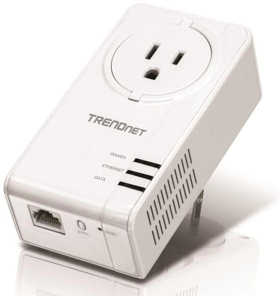 TRENDnet AV2 IP over AC powerlines modules provide up to 1,200 Mbps of LAN connectivity. (Source: TRENDnet)

Another innovative usage of AC/IP adapters is in the agricultural market, which is becoming increasingly technology-based.
In many cases the AC power to multiple buildings will connect the farm house to the remote barns and other structures on a farm. TRENDnet states that their AV2 AC/IP adapters will function over 950 feet of AC wiring. Installation companies can now extend IP/LAN connectivity to the remote buildings without costly buried or overhead cable installations. With the increased usage of wired and Wi-Fi IP connectivity to monitor livestock conditions, using the existing AC wiring to extend LAN connectivity makes economic sense.
Remote buildings that have AC power provided from a main building can be connected to a client’s LAN without the costly expense of direct burial or overhead cable installation.
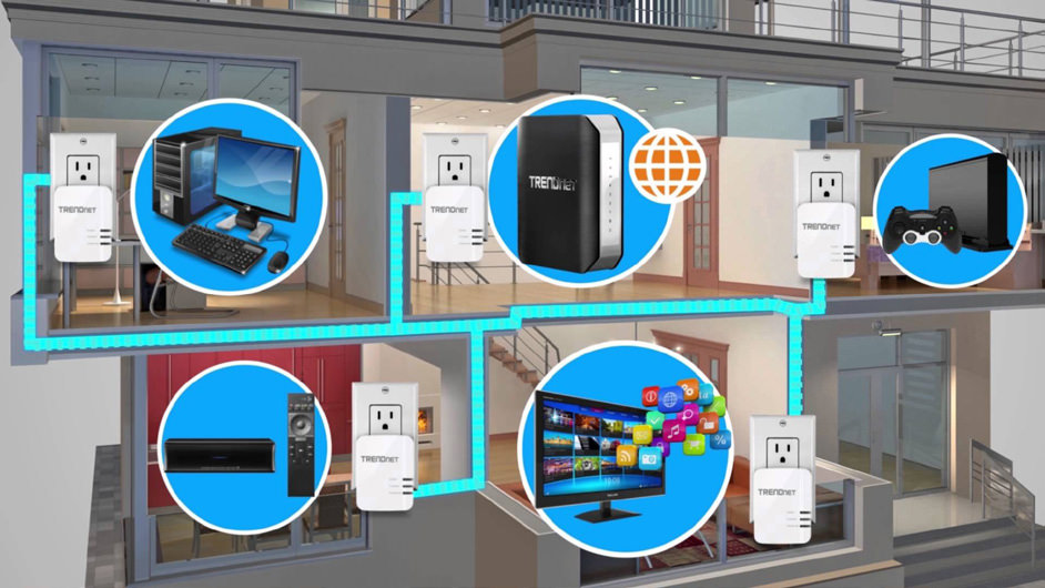
IP over AC modules can be used for many non-security applications, such as adding Wi-Fi access points and providing wired Ethernet connectivity without having to install new cabling. (Source: TRENDnet)
Future Possibilities for IP Adapter Technologies in Security Systems
There are a number of factors that point towards a rapid growth in the use of some of the technologies detailed in this report. The increases in the “loaded” cost of installation labor (salary, uniforms, insurance, vehicles, fuel, tools and licensing) will drive security installation companies to maximize the number of devices and systems that individual or teams of technicians can install in a given time. Adapter technologies will dramatically lower installation costs.
Another factor that will drive adapter technologies forward is the decreasing cost of the technologies from the manufacturers. As with all electronics, the more individual devices are produced, the lower the cost per unit, which will entice more security contractors to offer these technologies in their proposals.
Reduced installation time using IP adapters will also reduce the amount of disruption experienced by end users during an installation. Less cable pulling means the use of fewer ladders, cable boxes and tools to get in the customers’ way as they operate their business or institution.
The introduction of SFP (Small Form Factor Pluggable) sockets on network switches will enable quick and selectable LAN connectivity between telecom racks. Relatively inexpensive SFP modules are most commonly used to provide either single-mode or multimode fiber communications between switches. When security contractors are installing separate or parallel LAN networks for the communications of IP-enabled security devices, they can utilize existing “dark” or unlit fiber links to provide high-bandwidth connectivity between remote LAN network switches. As security contractors become more comfortable in using IP devices, the usage of SFP modules will increase.
Adapter technologies will be increasingly used by astute security contractors and will be specified by end users looking to save on cable installation costs. These technologies will allow end users to spend the vast majority of their electronic security budget on the technologies themselves, and not on cable-pulling labor, providing them with the opportunity to use the most advanced devices and services to help meet and exceed their security system needs.
David J. Engebretson (slaytonsolutions@sbcglobal.net) is president of Slayton Solutions Ltd.
